The design of Chebyshev lowpass filters involves very simple calculations as can be seen below. After first finding the necessary degree of the filter, the calculation of lumped elements is carried out as shown below. Note, that I use the perhaps more unfamiliar but very compact approach published by Saal & Ulbrich in their classic filter design paper of 1958.
Calculation of lumped (LC) elements:
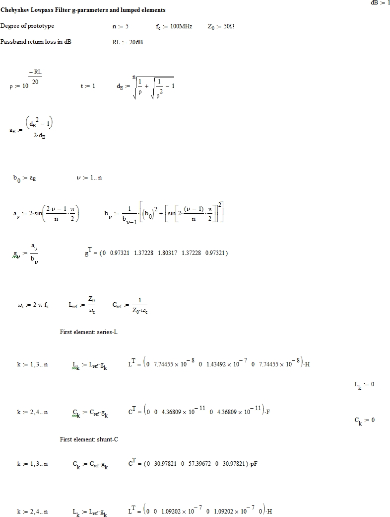
(Exponent “T” denotes the transposed data vector. Note, that the shunt capacitance units in the 2nd set of data are pF)
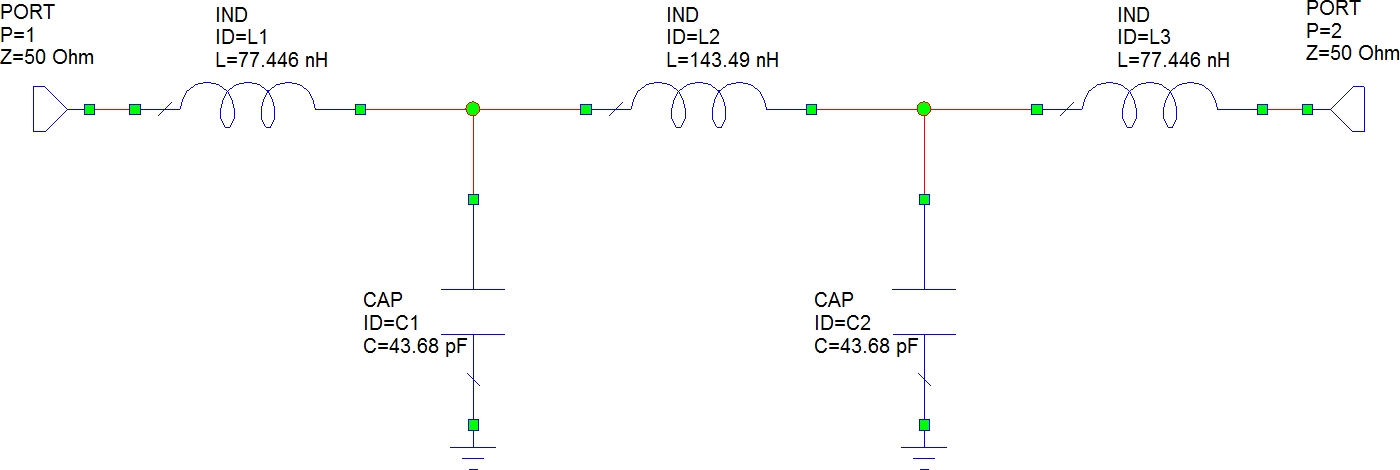
Lowpass filter circuit model – first element is a series-L:
Lowpass filter circuit model – first element is a shunt-C.
Duality allows us to obtain exactly the same filter response from a 2nd circuit with the same number of elements. Only the first element type and its connection to the source node changes (instead of a series-L, we start with a shunt-C – both create a transmission zero at f = infinity).
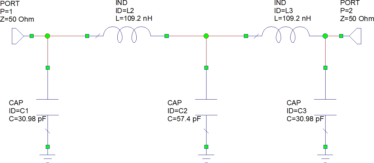
Circuit analysis of the two lowpass filter circuit models shown above yields exactly the same lowpass filter response:

Further comments on lowpass filters
There can be a variety of reasons for calculating lowpass filter LC elements.
- design of lumped element lowpass filters
- design of distributed element lowpass filters (conversion of LC elements to equivalent distributed elements with frequency limitation of equivalence)
- lumped element bandpass filter design by lowpass-to-bandpass transformation (LPF f=0 is transformed to BPF fc)
You may indeed need to design a lumped element lowpass filter and naturally you will then need to have the element values. The real elements in the form of capacitors and physical inductances (coils) will introduce new effects that usually become significant above the cutoff frequency of the lowpass filter:
- coil winding capacitance (can be concentrated as a parallel capacitance)
- capacitor physical lead conductors create effects like series inductances
- physical elements have finite quality factors that introduce losses
- higher order effects if f >> f_cutoff
All the above effects need to be considered when a LC lowpass filter is to be designed. For single-layer cylindrical coils the physical data can be found with high accuracy.
PLEASE CONSIDER MAKING A DONATION IF THIS PAGE WAS USEFUL TO YOU – THANKS !
[seamless-donations]