The port tuning method as an aid for filter design was first introduced by Dan Swanson at IMS-2001 in Phoenix/Arizona. It has since been adopted and refined by many filter designers. The versatile technique can be used for both planar and non-planar filter designs.
The electromagnetic simulation of bandpass filters is marked by the difficulty of resonator tuning. This difficulty arises from the strong sensitivity of the filter response to the resonator frequencies. Even an otherwise perfect bandpass filter will loose its good passband return loss immediately, if one or more resonators are slightly detuned. This of course is also the case with em models of bandpass filters – especially those with a narrow passband. Tuning diagnosis and improvement can however be achieved relatively easily if the so-called port tuning technique is used. The principle of this technique is a post-3d-em-simulation ‘tuning’ of a 3d em s-parameter file in a circuit simulator. For this purpose, the 3d em model contains additional ports located in the most frequency sensitive location of the filter resonators. This makes each resonator accessible in a circuit simulator via an exported .S2P data file for the purpose of lumped element tuning. The extra ports in the 3d em model are lumped ports defined across narrow 2d sheet objects in the 3d em model. These ports can then be loaded with lumped shunt capacitances in a circuit simulator and thereby the resonators become tunable in the circuit simulator. Additional series capacitances between each resonator node can be added for the purpose of coupling diagnosis and adjustment. Filter response optimisation is then possible in the circuit simulator and the resulting capacitance values reveal the tuning state of the 3d em model. The larger the tuning error of the 3d em filter model, the larger the capacitances in the circuit simulator. In this context one must keep in mind that both positive and negative capacitance values can be used in circuit simulation. A negative capacitance value indicates that the resonator of the em model is tuned too low. With regard to the series capacitances between the resonator nodes, the nature of the main coupling between the resonators must be kept in mind. If it is inductive coupling, then a positive series capacitance in the circuit simulator indicates that the coupling was too strong. On the basis of the knowledge of the tuning state of the filter, the 3d em model can then be improved if necessary. This process can be repeated until the capacitances in the circuit simulator become sufficiently small. Convergence of the technique is guaranteed if the changes in the em model are chosen wisely and not too large. Once the sensitivities of the resonators are known (kHz per mm) the tuning of the em model becomes very easy. Input and output coupling adjustment can be done in the em model while monitoring the capacitance values in the circuit simulator. Zero or minimum total capacitance indicates a proper tuning status of the em-model.
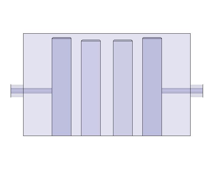
The process is illustrated below in a simple 4-resonator combline filter example:
(click on the figures to enlarge)
3d em model of a simple 4-resonator combline filter
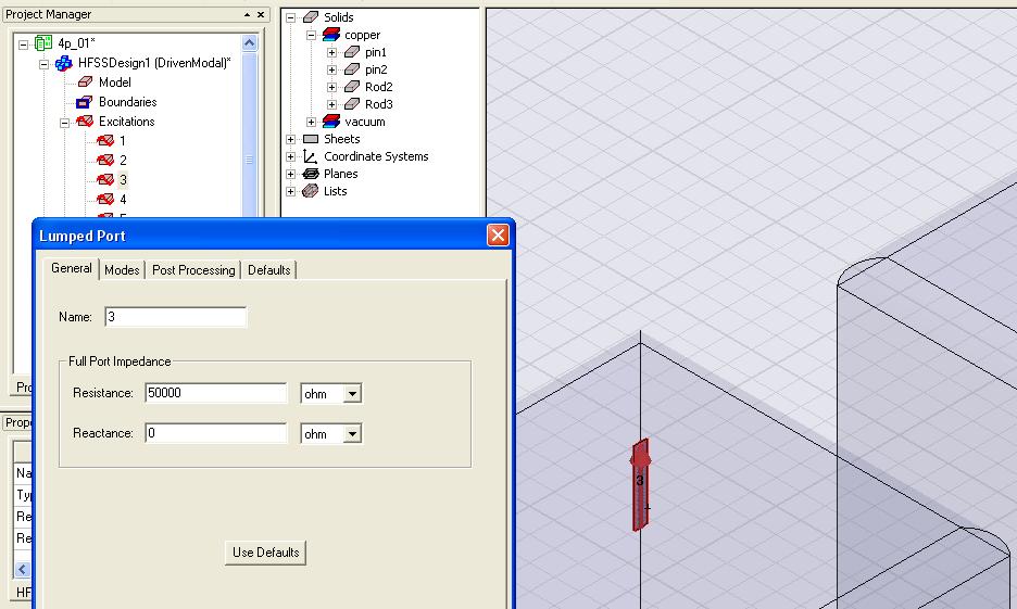
Insertion of extra lumped ports between the top face of the resonators and the upper lid of the filter (the high port impedance ensures that the simulated response is not affected by resistive loading from the port)


