No doubt, the unloaded Q of a filter resonator is one of the most important resonator parameters. What are the factors that govern the Q of a microstrip resonator ? This question led me to do some analysing and concluding. Based on the definition of the unloaded Q: stored energy / dissipated energy – it is possible and relatively easy to find out how the total dissipated energy is composed. How much energy is dissipated in the copper strip and how much in the substrate?
As a second step it would seem appropriate to find out at what stripline width the maximum Qu is obtained. Is there an optimal line impedance, similar to the case of coaxial TEM-mode air dielectric resonators? Well, the answer has to be a clear “no”. With reference to the graph below, we can see that as the losses in the copper decrease with increasing stripline width, the losses in the substrate increase due to the larger substrate area under the copper strip. A cancellation effect takes place and unlike with coaxial resonators, there is no visible unloaded Q maximum for resonators using typical substrate materials.
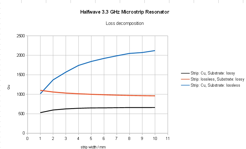
With all losses included (black curve) the Qu remains constant beyond a line width of 4mm. Similarly, when the strip material is lossless – except for a near constant Qu improvement. This clearly indicates that there is no optimal line impedance in microstrip halfwave resonators.
– to be continued –