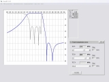
Filter responses can easily be created with just a little math. When first considering filter responses, it is absolutely unnecessary to analyse a filter circuit. In other words: you really don’t need a circuit simulator if you just want to plot a filter response, like S21 in dB. OK – you know you need a microstrip filter, but you surely don’t want to simulate a particular filter of a guessed degree, only to find out that it does not give you the rejection you need.
We can do a lot of initial work, like determining the degree of a filter, with relatively simple mathematical filter functions. These functions produce the same filter response that would be measured if the real filter existed – they comply with so-called realizability conditions. If the magnitude transfer function of a filter is known, then the frequency response of a filter is also known. Standard filter responses, like Chebyshev, Butterworth or maximally flat are mathematically very simple. But even the so-called quasi-elliptic function filters, sometimes also called General Chebyshev filters, have transfer functions which are mathematically relatively uncomplicated. One could argue that in the case of a General Chebyshev filter, the arbitrarily placed transmission zeroes (the attenuation ‘notches’ in the filter response) are a complication because the transfer function – in an equi-ripple passband sense – depends upon the location of the transmission zeroes in the filter passband. That complication is however overcome by using either of two clever methods that preserve the equi-ripple passband irrespective of the location of finite frequency transmission zeroes:
1. Transformed variable approach
2. General Chebyshev function approach
The modified Chebyshev function (see below) maintains the typical Chebyshev ‘equal ripple’ passband irrespective of the frequency placement of the transmission zeroes by using a suitable argument for the classic Chebyshev filter function. This really simplifies the design of this type of filter a lot. In true filter jargon: It simplified the ‘approximation’ part of the design job. By ‘approximation’ we mean here the mathematical approximation of an ideal filtering function, that fulfills a given filter specification using such functions that meet certain realizability conditions of passive networks. Ideal filter responses cannot be fulfilled by a realizable passive network. For example: zero dB insertion loss in the passband and then 60 dB rejection in an adjoining stopband – without any transition frequency gap. Therefore, the ideal filter response can only be approximated – although many modern bandpass filters with properly placed finite frequency transmission zeroes come very close to a desired ideal filter characteristic.
Earlier to this, the transformed variable approach existed for solving the approximation problem (Orchard & Temes, 1958). It is a straightforward method based upon transforming the reflection- and transmission zeroes (also called: loss poles) into a transformed variable domain. In this new domain, the equi-ripple passband property is then automatically maintained. Unlike the Cameron method for finding the polynomial coefficients, the transformed variable approach does not use a recursive technique. Chapter 6 by G. C. Temes in the book “Computer oriented circuit design” explains the transformed variable method (see list of text books).
Click to see Mathcad Calculation using Transformed Variable approach
Click to see Mathcad Calculation using General Chebyshev approach


